Thermostats and hygrostats for electrical enclosures
Thermostats and hygrostats switch the fan and the heater in the enclosure on only when needed. The equipment does not overheat, and when the cabinet cools down no condensation forms on the walls and circuit boards. Hygrostats are often sold as “hydrostats”.
Types
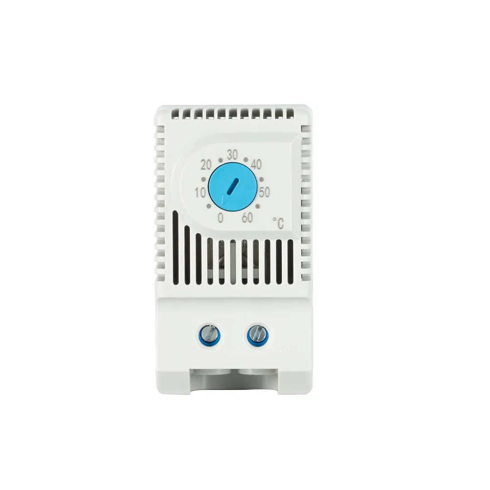
- Thermostat with NO contact (blue knob) — closes when the temperature rises above the setting and switches on the filter fan or heat exchanger.
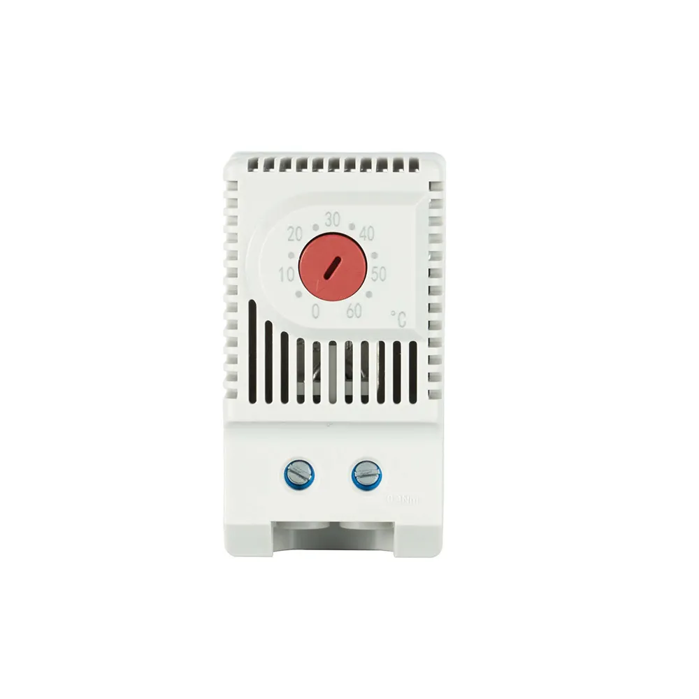
- Thermostat with NC contact (red knob) — opens when the temperature rises; below the setting it is closed and keeps the heater on.
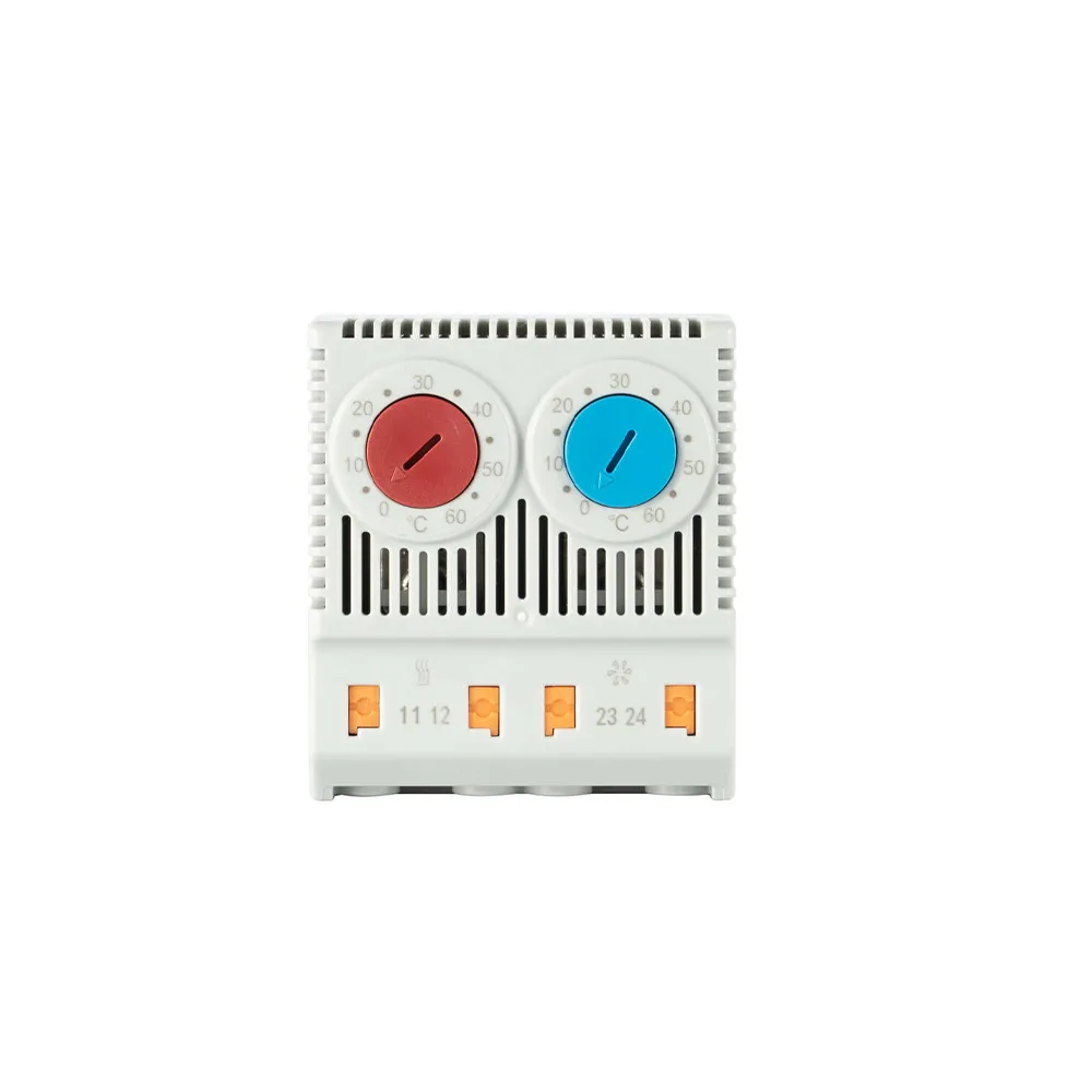
- Double thermostat — both parts in one housing with two independent settings: NC for the heater and NO for the fan.
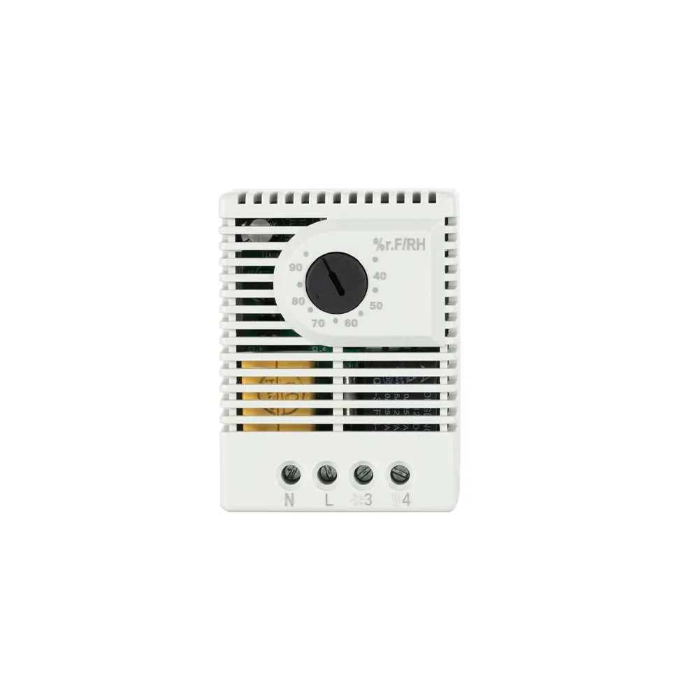
- Hygrostat — switches the heater on when the relative humidity reaches the setting. The critical humidity for most equipment is about 65 % RH.
Technical data
|
Thermostat NO / NC |
Double thermostat |
Hygrostat |
| Setting range |
0 … +60 °C |
0 … +60 °C (both parts) |
30 … 90 % RH |
| Hysteresis |
7 K (± 4 K) |
7 K (± 4 K) |
about 4 % RH |
| Switching capacity |
10 A / AC 230 V |
10 A / AC 230 V |
3 … 5 A at AC 230 / 250 V depending on the version |
| Sensor |
bimetal |
bimetal |
relative humidity sensor |
| Dimensions, mm |
60 × 33 × 43 |
69 × 50 × 46 |
67 × 50 × 38 |
| Mounting |
35 mm DIN rail; IP20 housing |
The switching capacity is given for a resistive load; for an inductive load (the fan motor) it is lower — 10 (2) A means 10 A resistive and 2 A inductive. If the load current exceeds it, the thermostat drives an interposing relay or contactor.
Wiring
The fan is controlled by the thermostat with the NO contact, the heater by the thermostat with the NC contact. The hygrostat is wired in parallel with the heater thermostat: it also switches the heater on at high humidity, before condensation occurs, even when the temperature is above the setting. The circuit is protected by a circuit breaker or fuse sized for the fan and heater current and the wire cross-section.
Installation and setting
- Thermostat — in the upper part of the cabinet, where the air is warmest, and away from the heater, otherwise it measures the heater's own heat.
- Heater — at the bottom, vertical, away from cables and ducts; the heat rises through the equipment.
- Filter fan — at the bottom, outlet filter — at the top on the opposite side; warm air collects at the top and leaves by itself.
- The fan is set below the permissible temperature of the most sensitive device in the cabinet, allowing for the hysteresis. The heater is set so that the cabinet stays above the dew point, and the hygrostat below the critical humidity.
If the outside air is warmer than allowed in the cabinet or is contaminated with oil or conductive dust, a fan does not help — an air conditioner or an air-to-air heat exchanger is needed.
Sizing the fan
The required airflow is V = f · Pv / ΔT, where V is the airflow, m³/h; Pv — the heat dissipated by the equipment in the cabinet (its losses, not the power consumed), W; ΔT — the permissible difference between the cabinet and room temperature, K; f — an altitude factor: 3.1 up to 100 m; 3.2 up to 250 m; 3.3 up to 500 m; 3.4 up to 750 m; 3.5 up to 1,000 m.
Example. Frequency inverters and power supplies dissipate Pv = 600 W; the room is up to +30 °C and the cabinet may reach +45 °C — ΔT = 15 K; the site is at 550 m (f = 3.4). V = 3.4 · 600 / 15 ≈ 136 m³/h. The fan is selected by its airflow with the outlet filter and with a margin, because the filter gets clogged.
Sizing the heater
The required power is P = A · k · ΔT, where A is the effective surface of the cabinet, m² (depends on how many walls are free); k — the heat transfer coefficient of the wall: 5.5 W/(m²·K) for painted steel, 4.5 for stainless steel, 12 for aluminium, 3.5 for plastic; ΔT — the difference between the desired cabinet temperature and the lowest outside temperature, K.
Example. Free-standing painted steel cabinet 2,000 × 800 × 600 mm, ΔT = 15 K: A = 1.8 · 2.0 · (0.8 + 0.6) + 1.4 · 0.8 · 0.6 ≈ 5.71 m²; P = 5.71 · 5.5 · 15 ≈ 471 W — a heater of 500 W or more. An outdoor cabinet needs about twice as much. The heater is sized for a stopped machine, when the equipment gives off no heat.
Related products
Filter fans, outlet filters, roof fans and enclosure heaters — in the category Accessories for electrical enclosures.
Send us the cabinet dimensions, the heat dissipated by the equipment and the site conditions — we will propose a fan, a heater and the control.